Pipe Wall Thickness
Pipe wall thickness calculation using Barlow´s formula
Pipe Wall Thickness
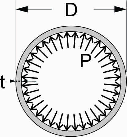
Barlow´s Formula is used to calculate the pipe pressure considering its diameter, wall thickness, and hoop stress (in the pipe material). Thus, it can be used to calculate whichever one of those parameters as a function of the other three.
In addition to some other simplifications, an important theoretical assumption made for the use of Barlow´s formula is that the pipe wall behaves like a membrane (or thin wall pipe), meaning the hoop stress in the pipe wall is distributed uniformly in all its thickness. There are no moments of any type within the pipe wall.One parameter to ensure that the membrane behavior happens in the pipe wall is the diameter over thickness ratio (D/t) to be bigger or equal to 20 1 2, although some authors consider 16 3.
However, the decision of using or not of the formula is usually not based on its section geometry (D/t ratio), but on the service of the pipe, considering the type of fluid, industry, and physical conditions, like for instance, the ASME (American Association of Mechanical Engineers) does.

- P: Pipe pressure
- S: Hoop stress
- t: Pipe wall thickness
- D: Outside diameter
Following that service criteria, the ASME B31.4 code (Pipeline Transportation Systems for Liquids and Slurries) applies the formula in this manner:
- A: Allowance for threading, grooving, corrosion
ASME B31.8 code (Gas Transmission and Distribution Piping Systems) applies it in this manner:
and to calculate the minimum wall thickness including an allowance:
it should be expressed like this:
- F: Design Factor
- E: Longitudinal Joint Factor
- T: Temperature Derating Factor
- A: Allowance for threading, grooving, corrosion
ASME B31.9 code (Building Services Piping) applies it in this manner:
- E: Longitudinal Joint Factor
- A: Allowance for threading, grooving, corrosion
On the other hand, as opposed to the thin wall assumption or membrane theory, there is the curved plate or thick wall pipe formulas derived from Lame´s theory whose use is more complicated, sometimes with iterations, and requires a careful approach like, for instance, in ASME B 31.1 code (Power Piping), ASME B 31.3 code (Process Piping), and ASME B 31.5 (Refrigeration Piping and Heat Transfer Components).
Comments